The CC1101 wireless RF transceiver from TI is a low-cost (~$4) wireless module that you can connect to your MCU (i.e. Arduino) and transmit/receive data at sub-1GHz frequencies (315/433/868/915 MHz) with support for various modulation formats (ASK, FSK, etc.). In this post I will use such a module to clone a common remote controlled outlet/switch, which operates at 433.95MHz.
Since the CC1101 is quite popular, you can obviously find tons of information on programming and using it. Although, none of the articles I came across describe the full procedure to initially identify the signal and then clone it using this module. That’s the main reason I decided to write about it.
Signal identification
First things first, identify the signal we want to clone. There are basically three ways to find out the signal specifications of our device.
- Check the model and/or the FCC ID (mostly available in the US) and get the information from the internet
- Tear down the remote control and try to figure out how it works
- Use SDR to find and identify our signal
Here we are going to try all three ways, mainly because the remote controlled switch I own is a no-name Chinese one with no manual or labels.
After popping up the case, on one side we can see an HS2260A encoder with some soldered inputs next to it (address and data lines) and on the other side a round crystal oscillator with “R433A” engraved on it.
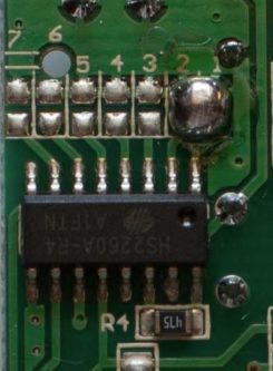
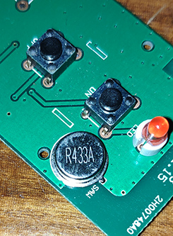
We most definitely know now that the frequency is around 433MHz, so we can just jump right onto our SDR and move on from there.
Use SDR to identify the signal
I am going to use a cheap RTL-SDR dongle for this, along with SDR#, but you are free to use any hardware (HackRF, BladeRF, etc.) with any software (e.g. HDSDR, GQRX). Just make sure you can record the transmitted samples of your remote.
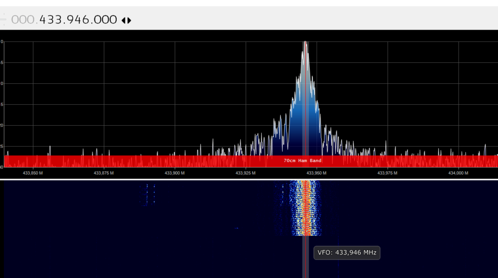
By pressing the remote control buttons a few times while observing the spectrum around 433MHz, I quickly find out that the exact frequency this remote transmits is 433.946MHz. Also, judging from the waterfall this probably seems like an ASK/OOK modulation. Setting this as my center frequency, I hit the record button in SDR# and then click the remote control buttons a few more times.
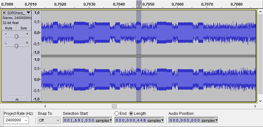
Let’s load the recorded file in Audacity and see what we can get from it.
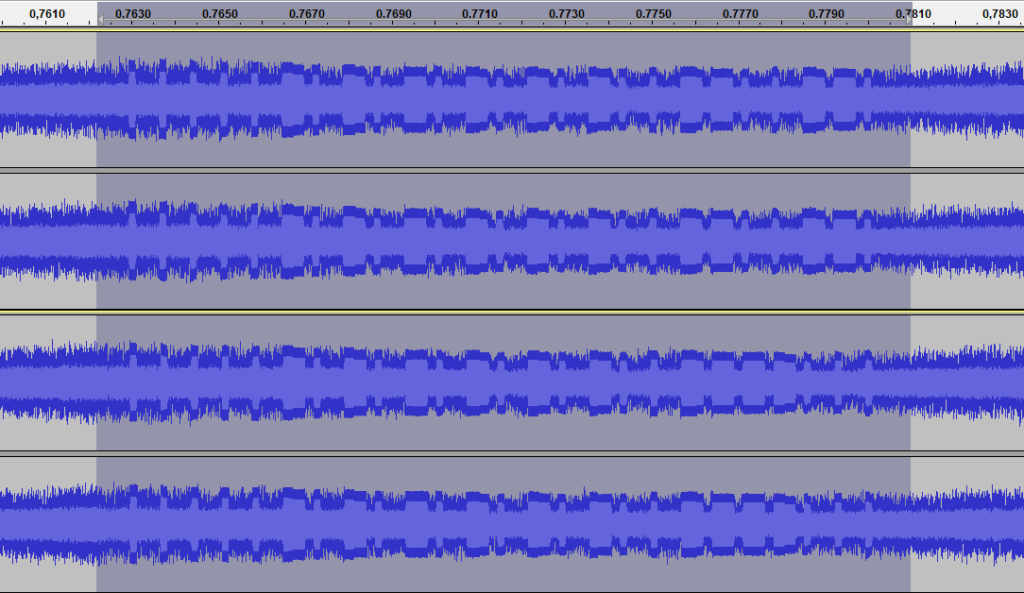
We can clearly see the transmitted pulses of the remote control. The top waveform is the signal for the ON button, while the bottom is the OFF one. They only differ in the last 5 pulses. Assuming that the short pulse equals with a ‘0’ symbol and the long pulse with an ‘1’, we can come up with the following sequences:
- ON:
0000010101010101001100110 - OFF:
0000010101010101001111000
In order to recreate those codes, we would need to convert these pulses to a real bit-stream. We can see that the high section of the ‘1’ symbol is almost three times the length of the high section of the ‘0’ symbol. Additionally, the low section of the ‘1’ symbol (after the long high) is almost equal with the high section of the ‘0’ symbol. If we suppose that we can represent each symbol with four digits/bits, we would essentially have 1000 for the ‘0’ and 1110 for the ‘1’. So, the above sequences become like that:
- ON: 1000100010001000100011101000111010001110100011101000111010001110100010001110111010001000111011101000 (or 0x88888E8E8E8E8E8E88EE88EE8)
- OFF: 1000100010001000100011101000111010001110100011101000111010001110100010001110111011101110100010001000 (or 0x88888E8E8E8E8E8E88EEEE888)
Up until now, we have the correct frequency, the correct bit-stream and we still need the baud rate and the actual duration of each digit, in order to fully recreate the transmission.
Staying in Audacity, we can measure the length of a single digit (e.g. the high section of the ‘0’ symbol) by selecting the corresponding section within the waveform, which is approximately 448 samples.
The baud rate (the rate at which a single digit is transmitted) can be calculated using the following formula:
Baud rate = 1 / (<samples_per_digit> / <recording_frequency>) = 1 / (448 / 2400000) = 5357
Likewise, the duration of a single digit is 448/2400000 = ~187usec. Thus, the duration of the entire code (or burst) is 187usec * 100 (number of digits) = 18700usec = 18.7msec, while the gap between these bursts is 11800 samples = 4916us ~= 5msec.
At this point we have completely analyzed the transmitted signals and we can move on to cloning them.
Cloning the signal using an Arduino (and a CC1101 module)
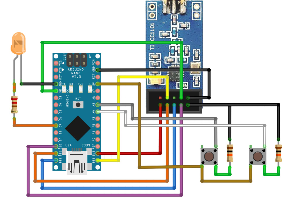
We are going to use an Arduino Nano v3.0 (~$3) with our CC1101 module to clone the signals, plus a couple of resistors, two buttons and an LED. The entire schematic is shown below.
Connections
| Arduino Nano v3.0 | CC1101 module |
|---|---|
| GND | GND |
| 3V3 | VCC |
| D2 | GD0 |
| D10 | CSN |
| D11 | SI |
| D12 | SO |
| D13 | SCK |
Additionally, I connected an LED on pin D7 of the Nano and two push buttons, one for the ON signal and one for the OFF signal, on pins A5 and A4 accordingly.
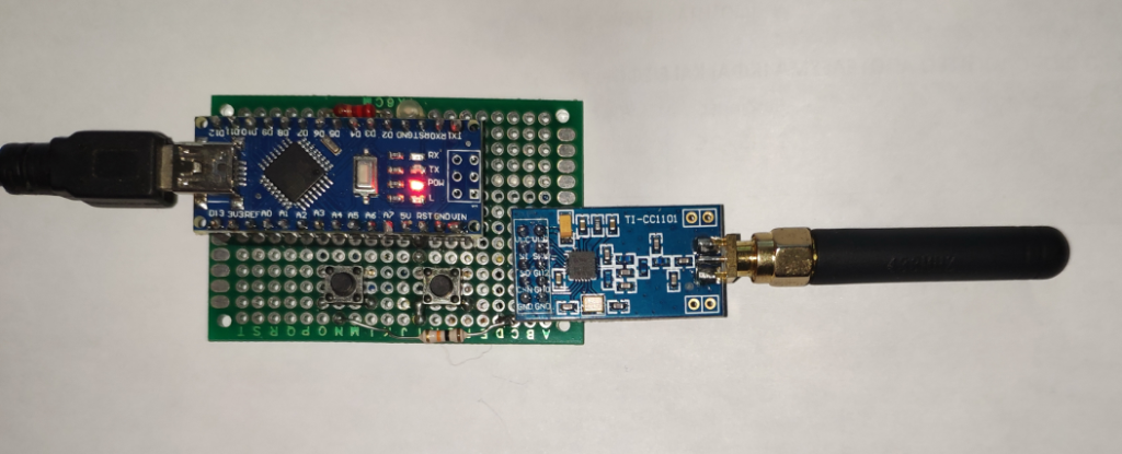
Here’s how my prototype looks like:
CC1101 Configuration
The CC1101 contains some registers that we need to configure programmatically, based on our findings above, in order to correctly transmit our signals. We are going to use a tool, that TI has developed, which can help us get the proper values of those registers, right through its GUI. If you require further information about these registers and the CC1101 itself, you should check the very detailed datasheet of CC1101, as well as the various application notes from TI.
After launching the SmartRF Studio by TI, under the CC1101 icon we select the “Open RF Device in Offline Mode” option.
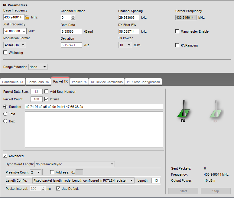
In the new window, ensuring that we are in “Expert Mode” to enable all options, we set the following RF Parameters:
- Base frequency: 433.946MHz
- Xtal frequency: 26MHz
- Modulation format: ASK/OOK
- Channel number: 0
- Data rate: 5.357 kBaud
- TX power: 10 dBm
and under the “Packet TX” tab, we set the Packet count to “Infinite”, with no seq. number and when we click the “Advanced” checkbox below, we also choose “No preamble/sync” and “Fixed packet length mode” with length of 13 bytes (number of bytes after we converted the code bit-stream to HEX).
Note that some of the above values will be automatically rounded, by the SmartRF software itself, to the closest acceptable ones. For example, we set our data rate to 5.357 kBaud and it gets automatically rounded to 5.35583 kBaud.
On the right side of the Device Control Panel, there is the “Register View” for the CC1101. There we click on the “Register Export” to get the list of the registers, in a nice formatted output, ready to be used in our program later on. In the “Register Export” window, I selected the “PA Table” checkbox and set the “Registers” input text box to the following:
cc1101.writeReg(CC1101_@RN@, 0x@VH@); @<<@// @Rd@
That way we got the following output:
 # PA table
 #define PA_TABLE {0x00,0xc0,0x00,0x00,0x00,0x00,0x00,0x00}
 //
 // Rf settings for CC1101
 //
 cc1101.writeReg(CC1101_IOCFG0, 0x06);   // GDO0 Output Pin Configuration
 cc1101.writeReg(CC1101_FIFOTHR, 0x47);  // RX FIFO and TX FIFO Thresholds
 cc1101.writeReg(CC1101_PKTLEN, 0x0D);   // Packet Length
 cc1101.writeReg(CC1101_PKTCTRL0, 0x00); // Packet Automation Control
 cc1101.writeReg(CC1101_FSCTRL1, 0x06);  // Frequency Synthesizer Control
 cc1101.writeReg(CC1101_FREQ2, 0x10);    // Frequency Control Word, High Byte
 cc1101.writeReg(CC1101_FREQ1, 0xB0);    // Frequency Control Word, Middle Byte
 cc1101.writeReg(CC1101_FREQ0, 0xB3);    // Frequency Control Word, Low Byte
 cc1101.writeReg(CC1101_MDMCFG4, 0xF7);  // Modem Configuration
 cc1101.writeReg(CC1101_MDMCFG3, 0xB0);  // Modem Configuration
 cc1101.writeReg(CC1101_MDMCFG2, 0x30);  // Modem Configuration
 cc1101.writeReg(CC1101_MDMCFG1, 0x00);  // Modem Configuration
 cc1101.writeReg(CC1101_MDMCFG0, 0x2E);  // Modem Configuration
 cc1101.writeReg(CC1101_DEVIATN, 0x15);  // Modem Deviation Setting
 cc1101.writeReg(CC1101_MCSM0, 0x14);    // Main Radio Control State Machine Configuration
 cc1101.writeReg(CC1101_FOCCFG, 0x16);   // Frequency Offset Compensation Configuration
 cc1101.writeReg(CC1101_WORCTRL, 0xFB);  // Wake On Radio Control
 cc1101.writeReg(CC1101_FREND0, 0x11);   // Front End TX Configuration
 cc1101.writeReg(CC1101_FSCAL3, 0xE9);   // Frequency Synthesizer Calibration
 cc1101.writeReg(CC1101_FSCAL2, 0x2A);   // Frequency Synthesizer Calibration
 cc1101.writeReg(CC1101_FSCAL1, 0x00);   // Frequency Synthesizer Calibration
 cc1101.writeReg(CC1101_FSCAL0, 0x1F);   // Frequency Synthesizer Calibration
 cc1101.writeReg(CC1101_TEST2, 0x81);    // Various Test Settings
 cc1101.writeReg(CC1101_TEST1, 0x35);    // Various Test Settings
 cc1101.writeReg(CC1101_TEST0, 0x09);    // Various Test Settings
Programming the Arduino Nano
In order for the Nano to talk (over SPI) with the CC1101, we are going to use the great library from Daniel Berenguer, which is part of the panstamp project.
Having the SPI library and the correct registers configuration, the rest of the code is trivial. In my case, I just had to select the option with the old bootloader under the Tools->Processor menu, before uploading the sketch to my Arduino Nano.
#include "cc1101.h"

#define LEDOUTPUT 7

CC1101 cc1101;

const int buttonPin1 = A5;
const int buttonPin2 = A4;

int button1State = 0;
int button2State = 0;

bool sending = false;

void blinker() {
  digitalWrite(LEDOUTPUT, HIGH);
  delay(100);
  digitalWrite(LEDOUTPUT, LOW);
  delay(100);
}

void setup()
{
  Serial.begin(9600);

  pinMode(LEDOUTPUT, OUTPUT);
  digitalWrite(LEDOUTPUT, LOW);

  pinMode(buttonPin1, INPUT);
  pinMode(buttonPin2, INPUT);

  // blink once
  blinker();

  Serial.println("Initializing CC1101.");
  cc1101.init();

  Serial.println("Setting up the PA_TABLE.");
  byte PA_TABLE[] = {0x00,0xc0,0x00,0x00,0x00,0x00,0x00,0x00}; // 10dBm
  cc1101.writeBurstReg(CC1101_PATABLE, PA_TABLE, 8);

  Serial.println("Setting up the registers.");
  cc1101_SetupRegisters();

  delay(1000);
  Serial.println("CC1101 initialized.");
}

void sendoncode() {
  byte ondata[13] = { 0x88, 0x88, 0x8E, 0x8E, 0x8E, 0x8E, 0x8E, 0x8E, 0x88, 0xEE, 0x88, 0xEE, 0x80 };
  sending = true;
  cc1101.sendData(ondata, 13);
  sending = false;
}

void sendoffcode() {
  byte offdata[13] = { 0x88, 0x88, 0x8E, 0x8E, 0x8E, 0x8E, 0x8E, 0x8E, 0x88, 0xEE, 0xEE, 0x88, 0x80 };
  sending = true;
  cc1101.sendData(offdata, 13);
  sending = false;
}

void loop()
{
  if (!sending) {
    button1State = digitalRead(buttonPin1);
    button2State = digitalRead(buttonPin2);

    if (button1State == HIGH) {
      Serial.println("Sending the on code");
      digitalWrite(LEDOUTPUT, HIGH);
      sendoncode();
      digitalWrite(LEDOUTPUT, LOW);
    }

    if (button2State == HIGH) {
      Serial.println("Sending the off code");
      digitalWrite(LEDOUTPUT, HIGH);
      sendoffcode();
      digitalWrite(LEDOUTPUT, LOW);
    }
  }
}

void cc1101_SetupRegisters() {
  //
  // Rf settings for CC1101
  //
  cc1101.writeReg(CC1101_IOCFG0, 0x06);   // GDO0 Output Pin Configuration
  cc1101.writeReg(CC1101_FIFOTHR, 0x47);  // RX FIFO and TX FIFO Thresholds
  cc1101.writeReg(CC1101_PKTLEN, 0x0D);   // Packet Length
  cc1101.writeReg(CC1101_PKTCTRL0, 0x00); // Packet Automation Control
  cc1101.writeReg(CC1101_FSCTRL1, 0x06);  // Frequency Synthesizer Control
  cc1101.writeReg(CC1101_FREQ2, 0x10);    // Frequency Control Word, High Byte
  cc1101.writeReg(CC1101_FREQ1, 0xB0);    // Frequency Control Word, Middle Byte
  cc1101.writeReg(CC1101_FREQ0, 0xB3);    // Frequency Control Word, Low Byte
  cc1101.writeReg(CC1101_MDMCFG4, 0xF7);  // Modem Configuration
  cc1101.writeReg(CC1101_MDMCFG3, 0xB0);  // Modem Configuration
  cc1101.writeReg(CC1101_MDMCFG2, 0x30);  // Modem Configuration
  cc1101.writeReg(CC1101_MDMCFG1, 0x00);  // Modem Configuration
  cc1101.writeReg(CC1101_MDMCFG0, 0x2E);  // Modem Configuration
  cc1101.writeReg(CC1101_DEVIATN, 0x15);  // Modem Deviation Setting
  cc1101.writeReg(CC1101_MCSM0, 0x14);    // Main Radio Control State Machine Configuration
  cc1101.writeReg(CC1101_FOCCFG, 0x16);   // Frequency Offset Compensation Configuration
  cc1101.writeReg(CC1101_WORCTRL, 0xFB);  // Wake On Radio Control
  cc1101.writeReg(CC1101_FREND0, 0x11);   // Front End TX Configuration
  cc1101.writeReg(CC1101_FSCAL3, 0xE9);   // Frequency Synthesizer Calibration
  cc1101.writeReg(CC1101_FSCAL2, 0x2A);   // Frequency Synthesizer Calibration
  cc1101.writeReg(CC1101_FSCAL1, 0x00);   // Frequency Synthesizer Calibration
  cc1101.writeReg(CC1101_FSCAL0, 0x1F);   // Frequency Synthesizer Calibration
  cc1101.writeReg(CC1101_TEST2, 0x81);    // Various Test Settings
  cc1101.writeReg(CC1101_TEST1, 0x35);    // Various Test Settings
  cc1101.writeReg(CC1101_TEST0, 0x09);    // Various Test Settings
}
The complete project, with the CC1101 library included, can be found in my GitHub.
Hi brother, I have an idea, but I’m not very familiar with programming. Can you improve this device, add a screen and a few more keys to make it support more functions and can be used offline, such as displaying the 2262 physical welding code directly on the screen. I have a few devices with similar functions here. Unfortunately, it is not cc1101. Please email me back if you are interested, thank you.
Awesome post, was very helpful for a beginner like me.
Sending data works well! (garage door opens)
But when I try to receive a from the remote, via receiveData()
I’m getting no signal at all.
Any ideas where I could be going wrong?
Hi,
This is exactly what I need. I tried it out but I’m stuck at this point:
Initializing CC1101.
Setting up the PA_TABLE.
Setting up the registers.
CC1101 initialized.
Sending the on code
Now the program seems to be stuck.
If I comment the send command like this:
sending = true;
//cc1101.sendData(ondata, 1);
sending = false;
then the serial monitor shows
Sending the on code
every 5 seconds as programmed.
Have you ever had this problem, too?
Every hint or support is very welcomed!!
Hey Stef,
If you comment out the sendData call, it will never send anything.
You mentioned that it loops every 5 seconds. Haven’t you used any trigger for sending, like a button?
Also, the second argument of the sendData in your example is 1. This means that your signal is just 1 byte long, which is very irregular. Especially at the receiving end where it certainly won’t catch your transmitted signal.
Do you have any SDR device to see if it transmits anything?
Great artical, built the hardwawe and used the software.
Used Universal Radio Hacker to get the code from my Chinees remote and it worked fine with Arduino Nano and the CR1101.
Of course you need a SDL radio, i used the RTL-SDT dongle which is a wondefull tool for RF experiments.
A lot of cc1101 software published at the Internet does not work, the OEM examples from ELECHOUS works fine but some people made extention libaries which wont work.
Anyway the example on the site works very good as a Chinese Key transmitter.
Thanks for making the site 🙂
Do you also have some code for a receiver for the CC1101, i cannot get the receiver to work with an cc1101 if i sent an RF signal from one of mine Chinese remote controls or from the TX setup as from your project.
I managed to recieve the code, but i had to use one of the cheaper chinese RF recievers which received my chinese remote and also from your TX setup.
For those interrested here is the Arduino code, connect the data pin from the radio receiver to pin 2 of the Arduino.
When it works you will see a lot of data appear, this is because i adapted the code a bit to see what happens:
Here is the code:
// Receives and displays data message formats for RF sensors
// Written by Boomer48: September 2019
// Modified by Otto Klaasen feb 2023 to work with Chinese Remote Control
//
// Input port for RF receiver data
#define Pulse_In 2 // INT0
// All times in microseconds
#define Min_Gap_Time 3000
#define Max_Gap_Time 16000
#define Min_Bit_Time 100
#define Max_Bit_Time 1500
#define Uncertainty 200 // Data bit pulse width uncertainty
byte RF_Bit_Count = 0;
byte RF_Byte_Count = 0;
byte RF_Byte = 0;
#define bit 8
char ASCII[] = “0123456789ABCDEF”;
byte RF_Message[] = {0, 0, 0, 0, 0, 0, 0};
byte RF_Invert_Message[] = {0, 0, 0, 0, 0, 0, 0};
String MyConvertedbyteString;
unsigned long Start_Time = 0;
int Pulse_Width;
byte Started = false;
int Gap_Time;
int Bit_Time1; // elapsed time of first bit
int Bit_Time2; // elapsed time of bit that mismatches first bit
byte Invert_Flg; // invert message byte if first bit was actually “0” instead of “1”
byte Msg_Complete;
String MsgCode;
void setup() {
Serial.begin(115200);
digitalWrite(Pulse_In, INPUT_PULLUP); //turn on pullup
Msg_Complete = false;
// Enable INT0 external interrupt, trigger on both edges
bitSet(EICRA, ISC00);
bitSet(EIMSK, INT0);
}
void loop() {
byte i;
byte temp;
if ((Msg_Complete == true) && (RF_Byte_Count > 2) && (RF_Byte_Count < 8)) {
noInterrupts();
Msg_Complete = false;
Serial.println("");
Serial.println("Start of loop and dumping timing parameters………");
Serial.write("Gap_Time: ");
Serial.print(Gap_Time);
Serial.write(" Bit_Time1: ");
Serial.print(Bit_Time1);
Serial.write(" Bit_Time2 ");
Serial.println(Bit_Time2);
Serial.print("RF_Byte_Count = ");Serial.println(RF_Byte_Count);
// Serial.write("Raw Bytes: ");
i = 0;
MsgCode = "";
while (i > 4]); // display upper nibble first
// Serial.print(“Upper Nibble = “);Serial.println(ASCII[RF_Message[i] >> 4]);
// Serial.write(ASCII[RF_Message[i] & 0x0F]);
// Serial.print(“Lower Nibble = “);Serial.println(ASCII[RF_Message[i] & 0x0F]);
MsgCode = MsgCode + ASCII[RF_Message[i] >> 4] + ASCII[RF_Message[i] & 0x0F];
// Serial.print(“MsgCode in loop = “);Serial.println(MsgCode);
i++;
}
Serial.println();
// Syntax
// bitRead(x, n)
// Parameters
// x: the number from which to read.
// n: which bit to read, starting at 0 for the least-significant (rightmost) bit.
MyConvertedbyteString =””;
for (int y = 0;y<3;y++){
Serial.print("RF_Message = ");Serial.println(RF_Message[y],BIN);
for (i=0;i<8;i++) {
Serial.print("Message 1 = ");Serial.println(bitRead(RF_Message[y],i),BIN);
Serial.print("i = ");Serial.println(i);
if (bitRead(RF_Message[y],i) == 0){
bitWrite(RF_Invert_Message[y],7-i,0);
}else{
bitWrite(RF_Invert_Message[y],7-i,1);
}
Serial.print("RF_Invert_Message2 = ");Serial.println(RF_Invert_Message[y],BIN);
}
Serial.print("RF_Invert_Message 2 HEX = ");Serial.println(RF_Invert_Message[y],HEX);
MyConvertedbyteString = String(RF_Invert_Message[y],HEX) + MyConvertedbyteString ;
}
// Dump complete code
MyConvertedbyteString.toUpperCase();
Serial.print("Decode Value = ");Serial.println(MyConvertedbyteString);
Serial.println("");
Serial.print("MsgCode by Arduino = ");Serial.println(MsgCode);
Serial.print("MsgCode = ");Serial.println(MsgCode);
if (MsgCode == "9F98E2") {Serial.println("Button B pressed !");}
if (MsgCode == "9F98E1") {Serial.println("Button A pressed !");}
Serial.println();
RF_Byte_Count = 0;
Started = false;
PCIFR = 0; // clear all pin change interrupt flags
interrupts();
}
} // end loop
// INT0 interrupt handler
ISR (INT0_vect)
{
//when the pin goes LOW record the pulse start time
if (digitalRead(Pulse_In) == LOW) {
Start_Time = micros();
}
else // pin went high
if (Start_Time != 0) {
//calculate the pulse width
Pulse_Width = ((volatile int)micros() – Start_Time);
//clear the timer
Start_Time = 0;
// Now check for valid message
if (Pulse_Width Min_Bit_Time) && (Pulse_Width (Bit_Time1 – Uncertainty)) && (Pulse_Width Bit_Time2)
Invert_Flg = true;
else
Invert_Flg = false;
}
}
}
else { // bad bit or end of message
if (Pulse_Width > Min_Gap_Time) {
Msg_Complete = true;
}
Started = false;
}
} // Started
else if (Pulse_Width > Min_Gap_Time) {
// start of message
Started = true;
RF_Byte_Count = 0;
RF_Bit_Count = 8;
Gap_Time = Pulse_Width; // save for display
Bit_Time1 = 0;
Bit_Time2 = 0;
}
}
else { // invalid message
Started = false;
}
}
}
Hi,
CC1101 is 3.3 volt compatible (not 5v-compat) and arduino nano is 5v. How can it work?
BR