BLE400 is a motherboard (development/evaluation kit) for the Core51822 (nRF51822) Bluetooth LE module (SoC). It costs around $13, with the BTLE module included.
This guide aims to help in building a basic program (blinky) for the nRF51822 SoC (ARM Cortex-M0) and flashing/programming it, using OpenOCD.
Although there is a mini USB connector on the BLE400, it can’t be used to flash the device since there is no debugger on the board (the on-board CP2102 is a UART to USB chip, not a debugger), so you need an external one in order to flash the nRF51822.
There are lots of guides that describe how to use a J-Link debugger/programmer with BLE400 and Keil uVision, which seems to be the default setup, but I wanted to make use of what I had at hand, a Bus Pirate. Same thing can be done using a Raspberry Pi. Both of these devices support the 2-pin SWD interface, that we can use with BLE400.
Core51822 is compatible with the PCA10001 evaluation kit from Nordic, so we will be using the blinky example of that board from the nRF51 SDK. The examples from pca10028 could also work, since it has the same specs (nrf51822_xxAA), but may need changes to the pin-out in the pca10028.h header file to depict the Core51822. Maybe pca20006 too.
Building blinky under Windows
First of all, we have to install MDK5 from Keil and the nRF5x_MDK_8_24_1_Keil4_NordicLicense from nRF5 SDK.
Then, get the latest nRF51 SDK (v.6.1.0) that supports the pca10001 board and extract nrf51822 folder into C:\Keil_v5\ARM\Device\Nordic\nRF51822 (or to whatever path where you installed MDK into).
In order for Keil uVision to find the required core_cm*.h files we can either launch uVision and add the path “C:\Keil_v5\ARM\Device\Nordic\nRF51822\Include\gcc” in Project -> Target options -> C/C++ -> “Include Paths” field or just move the files under subfolder gcc/* into Include (its parent folder).
Now let’s build the blinky project using Keil uVision in Windows.
Open the blinky project from C:\Keil_v5\ARM\Device\Nordic\nrf51822\Board\pca10001\blinky_example\arm\blinky.uvproj and run Project -> Rebuild all.
If everything went well, you should be able to find the built files in C:\Keil_v5\ARM\Device\Nordic\nrf51822\Board\pca10001\blinky_example\arm\_build.
We just want the hex file from that folder.
Building blinky under Linux
It seems that Nordic is not very much in favor with Linux, since cross-compiling the example programs of the nRF51 SDK without Keil uVision is quite painful. Even the source files of those examples are line-terminated with CRLF (Windows). Additionally, the SDK before v.6.x.x didn’t contain a Makefile for those examples, only a Keil uVision project file.
To be able to cross-compile ARM in Debian, we have to install the following packages:
apt-get install gcc-arm-none-eabi gcc-arm-none-eabi-source binutils-arm-none-eabi libnewlib-arm-none-eabi
Note: There were some problems compiling programs that were depending on newlib in other Linux distros, because it was newer. In Debian “stretch”, with the supplied newlib, I had no such issues.
Now, get the latest nRF51 SDK (v.6.1.0) that supports the pca10001 board and extract it.
You should now edit ./Source/template/gcc/Makefile.posix file and change those three lines matching your toolchain installation. For example, mine is:
GNU_INSTALL_ROOT := /usr
GNU_VERSION := 5.4.1
GNU_PREFIX := arm-none-eabi
Then, go to nrf51822/Board/pca10001/blinky_example/gcc directory and run make. It should compile without errors. You should end up with the built files under the _build sub-directory, where we only need the hex file.
Note: I was getting this error: “../main.c:25:20: fatal error: stdint.h: No such file or directory”, which I solved by copying the stdint-gcc.h over stdint.h, like so:
cp /usr/local/lib/gcc/arm-none-eabi/5.4.1/include/stdint-gcc.h /usr/local/lib/gcc/arm-none-eabi/5.4.1/include/stdint.h
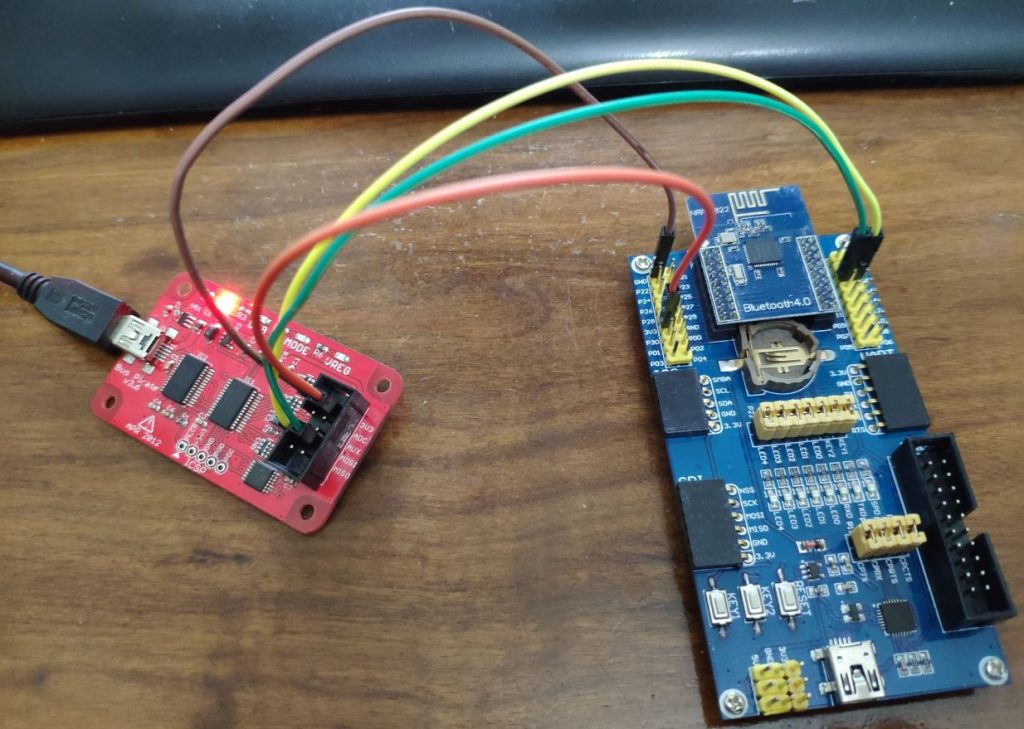
Flashing using Bus Pirate
We can connect the bus pirate to the BLE400 using the SWD interface that requires 2 pins and a common ground, plus the VCC if we want to power the nRF51822 from the bus pirate (alternatively, we can power it from the mini USB).
BLE400 motherboard contains an ARM Standard JTAG/SWD connector, where the three pins we want for SWD are pin 7 for SWDIO, pin 9 for SWCLK and one of the GND pins, e.g. pin 4. More info on the pin-out of the JTAG header can be found here.
We can also use the break-out pins next to the Core51822 module. Check the pin-out here. Let’s just use those.
| Bus pirate signal | BLE400 expansion pin |
|---|---|
| GND | GND |
| MOSI | SWIO / SWDIO |
| CLK | SWD / SWCLK |
| 3V3 | 3V3 |
Once the connections are done, let’s move on to the software side. As mentioned before, we are going to use OpenOCD to flash nRF51822 (target), with the bus pirate as the interface. In order to set up OpenOCD in a Debian distro, I had to follow the next steps.
Install the required packages.
apt-get install git libtool autotools autoconf automake texinfo pkg-config
Download OpenOCD v0.10.0 from sourceforge and extract.
wget -O openocd-0.10.0.tar.bz2 https://sourceforge.net/projects/openocd/files/openocd/0.10.0/openocd-0.10.0.tar.bz2/download
tar -jxvf openocd-0.10.0.tar.bz2
Since the native SWD interface isn’t working as it should with Bus Pirate and OpenOCD, we have to patch the source buspirate interface of OpenOCD to enable SWD via bit-banging, before compiling it.
cd openocd-0.10.0
wget https://the.earth.li/~noodles/bp-swd.diff
git apply bp-swd.diff
Now we can build OpenOCD.
./configure --enable-buspirate --enable-maintainer-mode
make
make install
Before we run openocd we have to specify the port of Bus Pirate (and enable the Voltage Regulator) by editing /usr/local/share/openocd/scripts/interface/buspirate.cfg. Here is mine:
#
# Buspirate with OpenOCD support
#
# http://dangerousprototypes.com/bus-pirate-manual/
#

interface buspirate

# you need to specify port on which BP lives
buspirate_port /dev/ttyUSB0

# voltage regulator Enabled = 1 Disabled = 0
buspirate_vreg 1

# pullup state Enabled = 1 Disabled = 0
#buspirate_pullup 0

# the following settings do not affect SWD mode

# communication speed setting
#buspirate_speed normal ;# or fast

# pin mode normal or open-drain
#buspirate_mode normal
We are now ready to launch openocd.
openocd -f /usr/local/share/openocd/scripts/interface/buspirate.cfg -c "transport select swd; set WORKAREASIZE 0" -f /usr/local/share/openocd/scripts/target/nrf51.cfg
If there were no errors, OpenOCD should now be listening on port 4444 for local connections.
Before we connect to it, if you built your program on Windows, copy the hex file into the Linux system we just set up OpenOCD.
Use telnet to connect to the 4444 TCP port to interact with OpenOCD.
telnet 0 4444
Once we are presented with the OpenOCD prompt, we can issue the following commands to flash our nRF51 chip.
init
reset
halt
nrf51 mass_erase
program /tmp/blinky_arm.hex verify
reset
shutdown
You should now see the LEDs called LED0 and LED1 on your BLE400, blink one after the other.
I should also mention that JTAG/SWD communication with Bus Pirate and OpenOCD is very slow! So in case you want to flash some small program (like blinky) it should be fine, but if you want to flash something bigger (like any BLE app with the SoftDevice) you’d better follow the Raspberry Pi guide below.
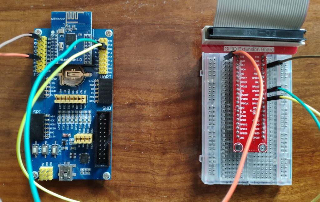
Flashing using Raspberry Pi
Let’s start by making the required connections between the Raspberry Pi and the BLE400 motherboard. I am using a Raspberry Pi 2.
| Raspberry Pi | BLE400 expansion pin |
|---|---|
| GND (e.g. pin 6) | GND |
| GPIO24 (pin 18) | SWIO / SWDIO |
| GPIO25 (pin 22) | SWD / SWCLK |
| 3V3 (pin 1 or 17) | 3V3 |
The procedure is quite similar to the one described for Bus Pirate, but takes place on the Raspberry Pi itself. I have a fresh install of Raspbian on it.
You can follow this guide from Adafruit to install openocd on the Raspberry Pi.
The we need to edit /usr/local/share/openocd/scripts/interface/raspberrypi2-native.cfg to match our connections. Specifically, we have to comment this out:
#bcm2835gpio_jtag_nums 11 25 10 9
and add our GPIO numbers here:
# Each of the SWD lines need a gpio number set: swclk swdio
bcm2835gpio_swd_nums 25 24
Then we can run OpenOCD.
sudo openocd -f interface/raspberrypi2-native.cfg -c "transport select swd; set WORKAREASIZE 0" -f target/nrf51.cfg
Next steps, are exactly the same as with the Bus Pirate. Telnet to local port 4444 and flash blinky.hex onto nRF51822. Just make sure you have copied your hex file to the Raspberry Pi.
 # telnet localhost 4444
 Trying 127.0.0.1...
 Connected to localhost.
 Escape character is '^]'.
 Open On-Chip Debugger
 > halt
 target halted due to debug-request, current mode: Thread
 xPSR: 0x81000000 pc: 0x000254ee msp: 0x20003ee0
 > nrf51 mass_erase
 > flash banks
 #0 : nrf51.flash (nrf51) at 0x00000000, size 0x00040000, buswidth 1, chi                                                                                                                                                                     pwidth 1
 #1 : nrf51.uicr (nrf51) at 0x10001000, size 0x00000100, buswidth 1, chip                                                                                                                                                                     width 1
 > program blinky.hex verify
 target halted due to debug-request, current mode: Thread
 xPSR: 0xc1000000 pc: 0xfffffffe msp: 0xfffffffc
 ** Programming Started **
 auto erase enabled
 not enough working area available(requested 32)
 no working area available, falling back to slow memory writes
 wrote 3072 bytes from file blinky.hex in 0.669635s (4.480 KiB/s)
 ** Programming Finished **
 ** Verify Started **
 not enough working area available(requested 52)
 verified 3052 bytes in 0.162138s (18.382 KiB/s)
 ** Verified OK **
 > reset run
Building more advanced examples
Most likely, with the BLE400, you will be needing more advanced programs, that utilize Bluetooth, and not just blinking LEDs.
In order to do so, you will have to also flash the Bluetooth LE protocol stack, known as SoftDevice, on your nRF51822.
Luckily, we can merge the SoftDevice and our program and flash it altogether onto our chip.
You can find SoftDevice S110 here and S120 here. The examples for pca10001 in the v6.x.x nRF51 SDK utilize the SoftDevice S110, so we will use that one, along with the ble_app_hrs example.
After you have compiled the ble_app_hrs example using Keil uVision you should end up with ble_app_hrs.hex file. Extract the S110 SoftDevice (s110_nrf51822_6.0.0_softdevice.hex) into the same directory. Then get the nRF5 Command Line Tools for your system from Nordic and extract the mergehex utility into the same directory as the hex files. We can now merge both hex files like that:
mergehex -m s110_nrf51822_6.0.0_softdevice.hex ble_app_hrs.hex -o hrs-combined.hex
Now you can flash the generated hrs-combined.hex file on the nRF51822 using the steps described in this post. Alternatively, you can just flash first the softdevice hex file and immediately after that the ble_app_hrs.hex file.
You can test the successful programming of the ble_app_hrs program with the nRF Toolbox app in your Android or iOS phone. After pairing and connecting with the “Nordic_HRM” device, select the HRM icon from the app and now you can use the buttons on the BLE400 to increase/decrease the BPM.
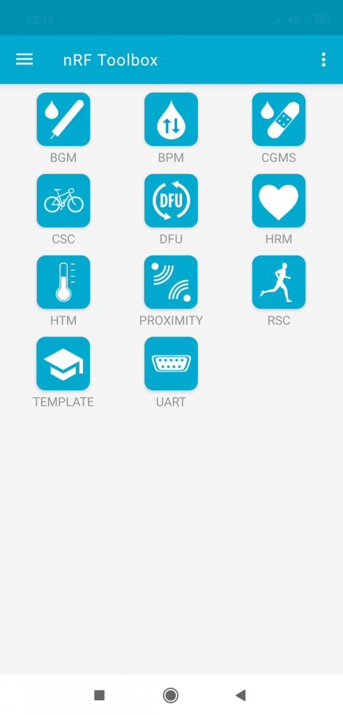
nRF Toolbox 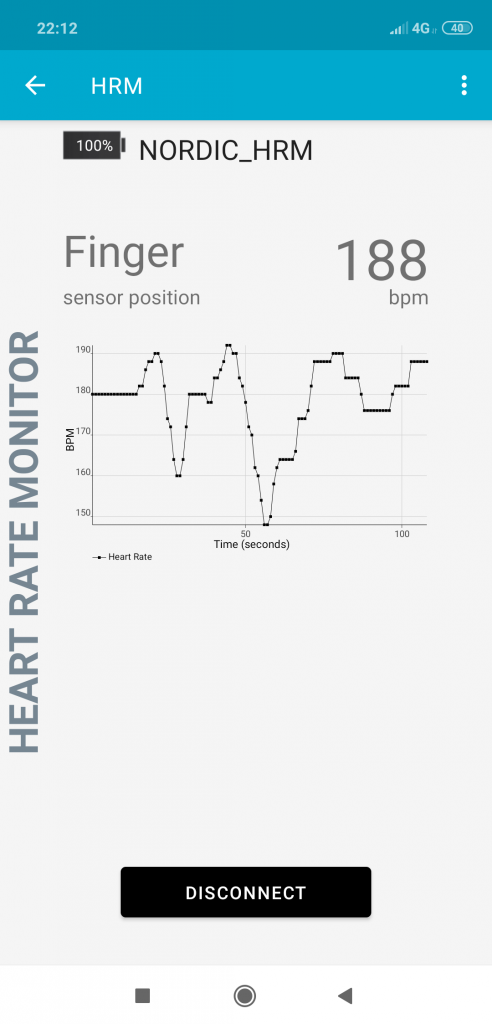
BLE HRM
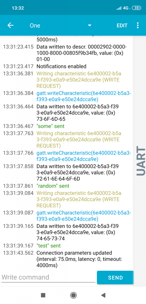
Another very useful example program from Nordic that we can flash is the ble_app_uart one, which is located under C:\Keil_v5\ARM\Device\Nordic\nrf51822\Board\pca10001\s110\experimental\ble_app_uart\ directory. After you compile it, you need to flash, again, first the softdevice hex and then the ble_app_uart.hex file or a merged one (using mergehex like before). You can now test it by opening a serial terminal (38400 baud rate) and, after connecting to the “Nordic_UART” BLE device, select the UART applet from the nRF Toolbox on your mobile. What you send from your mobile gets displayed on your serial terminal and vice-versa.
BLE UART 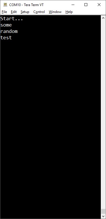
TermTerm serial terminal
Thanks, bookmarked! I will be following the basic idea and Linux software setup using an STLink programmer (I hope there’s no reason it won’t work!) soon.
I bought the BLE400 assuming it had a programmer/debugger built it (just saw the USB connection and assumed it was like the Nordic board)- pretty disappointed it doesn’t.
ST-Link should work without problems with SWD. Let me know how it went.
I had that same hope with the USB connector. At least there are alternatives to the lack of an on-board debugger.
It’s working great!
I am using the ST-LINK V2 with:
openocd -s /usr/share/openocd/scripts/ -f interface/stlink-v2.cfg -f target/nrf51_stlink.tcl
(with stock Ubuntu)
After blinky I tested successfully with the HRM and cadence examples from mbed. However somehow I can’t get a stupid simple HID keyboard example to work! (ultimately I want to build a special HID input device)
You could give a try to nrf6310\s110\ble_app_hids_keyboard example. Just remember to change the board definition to pca10001 and maybe also add the extra LED defines in pca10001.h file.
If the UART comm isn’t working, double-check the defined RX/TX pins.
Thanks for the suggestion. I got the ble_app_hids_keyboard working now with a newer version of the SDK (v10).
Thank you!!1